

Did Sps Services Take Over Casper Loans
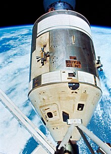
 Apollo CSM Endeavour in lunar orbit during Apollo 15 | |||
| Manufacturer | North American Aviation Due north American Rockwell | ||
|---|---|---|---|
| Designer | Maxime Faget | ||
| Country of origin | Us | ||
| Operator | NASA | ||
| Applications | Crewed cislunar flight and lunar orbit Skylab crew shuttle Apollo-Soyuz Test Projection | ||
| Specifications | |||
| Spacecraft blazon | Capsule | ||
| Launch mass | 32,390 lb (14,690 kg) Earth orbit 63,500 lb (28,800 kg) Lunar | ||
| Dry mass | 26,300 lb (xi,900 kg) | ||
| Payload capacity | 2,320 lb (ane,050 kg) | ||
| Crew capacity | iii | ||
| Volume | 218 cu ft (six.ii miii) | ||
| Ability | Fuel cells | ||
| Regime | Low Earth orbit Cislunar space Lunar orbit | ||
| Design life | fourteen days | ||
| Dimensions | |||
| Length | 36.ii ft (11.0 grand) | ||
| Bore | 12.eight ft (3.ix yard) | ||
| Production | |||
| Condition | Retired | ||
| Built | 35 | ||
| Launched | 19 | ||
| Operational | 19 | ||
| Failed | 2 | ||
| Lost | 1 | ||
| Maiden launch | February 26, 1966 (Equally-201) | ||
| Concluding launch | July 15, 1975 (Apollo-Soyuz) | ||
| Last retirement | July 24, 1975 | ||
| Service Propulsion System (Lunar descent help)[1] | |||
| Powered by | 1 AJ10-137 | ||
| Maximum thrust | 91.19 kN (20,500 lbf) | ||
| Specific impulse | 314.5 seconds (3.084 km/s) | ||
| Burn time | 750 due south | ||
| Propellant | Aerozine 50/North2O4 | ||
| Related spacecraft | |||
| Flown with | Apollo Lunar Module | ||
| Configuration | |||
 Apollo Block 2 CSM diagram
| |||
The Apollo command and service module (CSM) was one of ii principal components of the United states Apollo spacecraft, used for the Apollo program, which landed astronauts on the Moon between 1969 and 1972. The CSM functioned as a mother ship, which carried a coiffure of iii astronauts and the second Apollo spacecraft, the Apollo Lunar Module, to lunar orbit, and brought the astronauts back to Earth. It consisted of ii parts: the conical command module, a cabin that housed the crew and carried equipment needed for atmospheric reentry and splashdown; and the cylindrical service module which provided propulsion, electrical ability and storage for various consumables required during a mission. An umbilical connection transferred power and consumables betwixt the two modules. Just before reentry of the command module on the return home, the umbilical connection was severed and the service module was bandage off and allowed to burn up in the atmosphere.
The CSM was developed and built for NASA by N American Aviation starting in November 1961. Information technology was initially designed to state on the Moon atop a landing rocket stage and return all iii astronauts on a direct-rise mission, which would not apply a separate lunar module, and thus had no provisions for docking with another spacecraft. This, plus other required design changes, led to the conclusion to design ii versions of the CSM: Cake I was to be used for uncrewed missions and a unmarried crewed Earth orbit flying (Apollo i), while the more advanced Block II was designed for use with the lunar module. The Apollo 1 flight was cancelled afterward a cabin burn killed the crew and destroyed their command module during a launch rehearsal test. Corrections of the problems which acquired the burn were practical to the Block II spacecraft, which was used for all crewed spaceflights.
Nineteen CSMs were launched into space. Of these, nine flew humans to the Moon betwixt 1968 and 1972, and another two performed crewed exam flights in low Earth orbit, all as office of the Apollo program. Before these, another four CSMs had flown as uncrewed Apollo tests, of which two were suborbital flights and another ii were orbital flights. Following the conclusion of the Apollo programme and during 1973–1974, three CSMs ferried astronauts to the orbital Skylab space station. Finally in 1975, the last flown CSM docked with the Soviet arts and crafts Soyuz 19 as function of the international Apollo–Soyuz Test Project.
Before Apollo [edit]
Concepts of an advanced crewed spacecraft started before the Moon landing goal was appear. The three person vehicle was to be mainly for orbital use around earth. It would include a large pressurized auxiliary orbital module where the crew would live and work in for weeks at a fourth dimension. They would perform space station type activities in the module while after versions would use the module to carry cargo to space stations. The spacecraft was to service the Projection Olympus (LORL), a single launched foldable rotating space station launched on a single Saturn V. Afterward versions would be used on circumlunar flights and would be the basis for a direct ascent lunar spacecraft equally well as use on interplanetary missions. In late 1960, NASA chosen on U.S. industry to propose designs for the vehicle. On May 25, 1961 President John F. Kennedy announced the Moon landing goal before 1970, which completely bypassed NASA's Earth orbital Olympus Station plans.[2] [3]
Development history [edit]
When NASA awarded the initial Apollo contract to Northward American Aviation on November 28, 1961, it was still assumed the lunar landing would be achieved past straight ascent rather than by lunar orbit rendezvous.[iv] Therefore, design proceeded without a means of docking the command module to a lunar circuit module (LEM). Simply the change to lunar orbit rendezvous, plus several technical obstacles encountered in some subsystems (such as ecology control), before long made it clear that substantial redesign would be required. In 1963, NASA decided the virtually efficient way to continue the program on track was to proceed with the development in two versions:[5]
- Block I would go on the preliminary design, to be used for early low Earth orbit test flights only.
- Block 2 would exist the lunar-capable version, including a docking hatch and incorporating weight reduction and lessons learned in Block I. Detailed pattern of the docking capability depended on design of the LEM, which was contracted to Grumman Aircraft Engineering.
By Jan 1964, North American started presenting Cake II blueprint details to NASA.[vi] Cake I spacecraft were used for all uncrewed Saturn 1B and Saturn V test flights. Initially ii crewed flights were planned, but this was reduced to one in tardily 1966. This mission, designated Every bit-204 just named Apollo 1 past its flight coiffure, was planned for launch on Feb 21, 1967. During a dress rehearsal for the launch on January 27, all three astronauts (Gus Grissom, Ed White and Roger Chaffee) were killed in a cabin fire, which revealed serious design, structure and maintenance shortcomings in Block I, many of which had been carried over into Block II command modules being built at the fourth dimension.
After a thorough investigation by the Apollo 204 Review Board, it was decided to terminate the crewed Block I phase and redefine Block II to incorporate the review lath's recommendations. Block II incorporated a revised CM heat shield design, which was tested on the uncrewed Apollo iv and Apollo 6 flights, then the first all-up Cake II spacecraft flew on the first crewed mission, Apollo vii.
The 2 blocks were essentially like in overall dimensions, but several blueprint improvements resulted in weight reduction in Block II. As well, the Block I service module propellant tanks were slightly larger than in Block Ii. The Apollo 1 spacecraft weighed approximately 45,000 pounds (twenty,000 kg), while the Cake Two Apollo vii weighed 36,400 lb (16,500 kg). (These 2 World orbital craft were lighter than the arts and crafts which later went to the Moon, equally they carried propellant in only one set of tanks, and did not acquit the high-proceeds Southward-band antenna.) In the specifications given below, unless otherwise noted, all weights given are for the Block 2 spacecraft.
The total price of the CSM for development and the units produced was $36.9billion in 2016 dollars, adjusted from a nominal total of $3.seven billion[7] using the NASA New Offset Inflation Indices.[8]
Control module (CM) [edit]

Control module interior arrangement
The command module was a truncated cone (frustum) with a diameter of 12 feet x inches (3.91 m) beyond the base of operations, and a meridian of 11 feet 5 inches (3.48 m) including the docking probe and dish-shaped aft heat shield. The forwards compartment independent two reaction control organization thrusters, the docking tunnel, and the Earth Landing System. The inner force per unit area vessel housed the crew adaptation, equipment bays, controls and displays, and many spacecraft systems. The aft compartment contained x reaction control engines and their related propellant tanks, fresh h2o tanks, and the CSM umbilical cables.[9]
Construction [edit]
The command module consisted of 2 basic structures joined together: the inner structure (pressure crush) and the outer construction.
The inner construction was an aluminum sandwich construction consisting of a welded aluminum inner pare, adhesively bonded aluminum honeycomb cadre, and outer face sheet. The thickness of the honeycomb varied from almost ane.5 inches (three.8 cm) at the base to about 0.25 inches (0.64 cm) at the forward access tunnel. This inner structure was the pressurized crew compartment.
The outer structure was fabricated of stainless steel brazed-honeycomb brazed between steel alloy face sheets. Information technology varied in thickness from 0.5 inch to 2.5 inches. Part of the expanse between the inner and outer shells was filled with a layer of fiberglass insulation as additional heat protection.[ten]
Thermal protection (rut shield) [edit]

Control module reentering the atmosphere at a non-zero angle of attack in order to institute a lifting entry and control the landing site (creative rendition)
An ablative heat shield on the exterior of the CM protected the sheathing from the heat of reentry, which is sufficient to cook well-nigh metals. This heat shield was composed of phenolic formaldehyde resin. During reentry, this material charred and melted away, absorbing and conveying away the intense rut in the process. The heat shield has several outer coverings: a pore seal, a moisture barrier (a white reflective coating), and a silver Mylar thermal coating that looks like aluminum foil.
The rut shield varied in thickness from 2 inches (v.1 cm) in the aft portion (the base of the capsule, which faced forrard during reentry) to 0.five inches (one.iii cm) in the crew compartment and forrard portions. Full weight of the shield was about 3,000 pounds (1,400 kg).[x]
Forward compartment [edit]
The ane-foot-xi-inch (0.58 m)-tall forward compartment was the surface area outside the inner pressure shell in the nose of the capsule, located around the frontwards docking tunnel and covered by the forrad heat shield. The compartment was divided into four 90-degree segments that contained World landing equipment (all the parachutes, recovery antennas and beacon light, and bounding main recovery sling), 2 reaction command thrusters, and the forward heat shield release mechanism.
At about 25,000 feet (7,600 m) during reentry, the forward heat shield was jettisoned to expose the Earth landing equipment and permit deployment of the parachutes.[10]
Aft compartment [edit]
The 1-foot-8-inch (0.51 m)-tall aft compartment was located around the periphery of the command module at its widest part, merely forward of (above) the aft heat shield. The compartment was divided into 24 bays containing 10 reaction control engines; the fuel, oxidizer, and helium tanks for the CM reaction control subsystem; h2o tanks; the crushable ribs of the impact attenuation system; and a number of instruments. The CM-SM umbilical, the point where wiring and plumbing ran from one module to the other, was too in the aft compartment. The panels of the heat shield covering the aft compartment were removable for maintenance of the equipment earlier flight.[ten]
Globe landing system [edit]

Scale model of the Apollo command and service module at the Euro Space Middle in Kingdom of belgium

The Apollo fifteen Command Module splashes down in the Pacific Ocean, 1971.
The components of the ELS were housed around the frontward docking tunnel. The forrard compartment was separated from the central by a bulkhead and was divided into four xc-caste wedges. The ELS consisted of ii drogue parachutes with mortars, iii main parachutes, three airplane pilot parachutes to deploy the mains, 3 inflation bags for uprighting the sheathing if necessary, a sea recovery cable, a dye mark, and a swimmer umbilical.
The control module'south middle of mass was offset a foot or so from the center of pressure level (along the symmetry centrality). This provided a rotational moment during reentry, line-fishing the capsule and providing some lift (a lift to elevate ratio of about 0.368[11]). The capsule was then steered by rotating the capsule using thrusters; when no steering was required, the sheathing was spun slowly, and the lift effects cancelled out. This system greatly reduced the g-forcefulness experienced past the astronauts, permitted a reasonable amount of directional command and immune the sheathing'southward splashdown point to be targeted within a few miles.
At 24,000 feet (7,300 1000), the forward estrus shield was jettisoned using four pressurized-gas compression springs. The drogue parachutes were then deployed, slowing the spacecraft to 125 miles per hour (201 kilometres per hour). At 10,700 feet (iii,300 m) the drogues were jettisoned and the pilot parachutes, which pulled out the mains, were deployed. These slowed the CM to 22 miles per hr (35 kilometres per hour) for splashdown. The portion of the capsule that first contacted the water surface contained four crushable ribs to farther mitigate the force of touch on. The command module could safely parachute to an body of water landing with simply two parachutes deployed (equally occurred on Apollo 15), the tertiary parachute beingness a safety precaution.
Reaction control system [edit]
The control module attitude control system consisted of twelve 93-pound-force (410 N) attitude control thrusters, ten of which were located in the aft compartment, plus two in the forwards compartment. These were supplied past four tanks storing 270 pounds (120 kg) of monomethylhydrazine fuel and nitrogen tetroxide oxidizer, and pressurized by ane.1 pounds (0.l kg) of helium stored at 4,150 pounds per square inch (28.six MPa) in ii tanks.[ citation needed ]
Hatches [edit]
The forward docking hatch was mounted at the superlative of the docking tunnel. Information technology was 30 inches (76 cm) in diameter and weighed fourscore pounds (36 kg), constructed from two machined rings that were weld-joined to a brazed honeycomb panel. The exterior side was covered with 0.5-inch (13 mm) of insulation and a layer of aluminum foil. Information technology was latched in vi places and operated by a pump handle. The hatch contained a valve in its center, used to equalize the pressure between the tunnel and the CM and then the hatch could be removed.
The unified coiffure hatch (UCH) measured 29 inches (74 cm) loftier, 34 inches (86 cm) broad, and weighed 225 pounds (102 kg). It was operated by a pump handle, which drove a ratchet mechanism to open or close fifteen latches simultaneously.
Docking assembly [edit]
Apollo'due south mission required the LM to dock with the CSM on return from the Moon, and also in the transposition, docking, and extraction maneuver at the beginning of the translunar declension. The docking machinery was a non-androgynous organisation, consisting of a probe located in the nose of the CSM, which connected to the drogue, a truncated cone located on the lunar module. The probe was extended like a scissor jack to capture the drogue on initial contact, known as soft docking. Then the probe was retracted to pull the vehicles together and establish a firm connexion, known as "hard docking". The mechanism was specified by NASA to accept the following functions:[ citation needed ]
- Allow the two vehicles to connect, and attenuate excess movement and energy caused by docking
- Align and center the two vehicles and pull them together for capture
- Provide a rigid structural connexion between both vehicles, and be capable of removal and re-installation past a single crewman
- Provide a ways of remote separation of both vehicles for the return to World, using pyrotechnic fasteners at the circumference of the CSM docking collar
- Provide redundant power and logic circuits for all electrical and pyrotechnic components.
Coupling [edit]
The probe head located in the CSM was self-centering and gimbal-mounted to the probe piston. As the probe head engaged in the opening of the drogue socket, 3 spring-loaded latches depressed and engaged. These latches allowed a and then-called 'soft dock' state and enabled the pitch and yaw movements in the two vehicles to subside. Excess motion in the vehicles during the 'difficult dock' procedure could crusade impairment to the docking ring and put stress on the upper tunnel. A depressed locking trigger link at each latch immune a leap-loaded spool to move forrad, maintaining the toggle linkage in an over-center locked position. In the upper end of the lunar module tunnel, the drogue, which was synthetic of one-inch-thick aluminum honeycomb core, bonded forepart and dorsum to aluminum face sheets, was the receiving end of the probe head capture latches.
Retraction [edit]
After the initial capture and stabilization of the vehicles, the probe was capable of exerting a endmost force of ane,000 pounds-force (4.4 kN) to draw the vehicles together. This forcefulness was generated by gas pressure acting on the eye piston within the probe cylinder. Piston retraction compressed the probe and interface seals and actuated the 12 automatic ring latches which were located radially around the inner surface of the CSM docking ring. The latches were manually re-cocked in the docking tunnel by an astronaut later on each hard docking event (lunar missions required 2 dockings).
Separation [edit]
An automatic extension latch fastened to the probe cylinder torso engaged and retained the probe center piston in the retracted position. Before vehicle separation in lunar orbit, transmission cocking of the twelve ring latches was accomplished. The separating force from the internal pressure in the tunnel area was and then transmitted from the band latches to the probe and drogue. In undocking, the release of the capture latches was accomplished by electrically energizing tandem-mounted DC rotary solenoids located in the center piston. In a temperature degraded condition, a single motor release functioning was washed manually in the lunar module by depressing the locking spool through an open hole in the probe heads, while release from the CSM was done by rotating a release handle at the back of the probe to rotate the motor torque shaft manually.[12] When the command and lunar modules separated for the last time, the probe and forrard docking ring were pyrotechnically separated, leaving all docking equipment fastened to the lunar module. In the result of an arrest during launch from World, the aforementioned system would have explosively jettisoned the docking ring and probe from the CM every bit it separated from the boost protective comprehend.
Cabin interior organization [edit]

The central pressure vessel of the command module was its sole habitable compartment. It had an interior volume of 210 cubic feet (5.nine thou3) and housed the primary control panels, coiffure seats, guidance and navigation systems, food and equipment lockers, the waste management organization, and the docking tunnel.
Dominating the frontwards section of the cabin was the crescent-shaped main display panel measuring nearly 7 feet (2.1 yard) wide and 3 anxiety (0.91 thousand) tall. It was arranged into three panels, each emphasizing the duties of each crew member. The mission commander's console (left side) included the velocity, attitude, and distance indicators, the main flying controls, and the principal FDAI (Flying Director Attitude Indicator).
The CM pilot served as navigator, so his control panel (center) included the Guidance and Navigation computer controls, the caution and warning indicator console, the event timer, the Service Propulsion System and RCS controls, and the environmental control system controls.
The LM airplane pilot served every bit systems engineer, so his control panel (right-hand side) included the fuel cell gauges and controls, the electric and bombardment controls, and the communications controls.
Flanking the sides of the main panel were sets of smaller control panels. On the left side were a circuit breaker panel, audio controls, and the SCS ability controls. On the right were additional circuit breakers and a redundant audio command console, along with the ecology control switches. In total, the command module panels included 24 instruments, 566 switches, 40 effect indicators, and 71 lights.
The three crew couches were synthetic from hollow steel tubing and covered in a heavy, fireproof cloth known equally Armalon. The leg pans of the two outer couches could be folded in a variety of positions, while the hip pan of the center couch could be disconnected and laid on the aft bulkhead. One rotation and one translation hand controller was installed on the armrests of the left-hand couch. The translation controller was used past the crew fellow member performing the transposition, docking, and extraction maneuver with the LM, usually the CM Airplane pilot. The center and correct-hand couches had duplicate rotational controllers. The couches were supported by eight stupor-attenuating struts, designed to ease the impact of touchdown on water or, in instance of an emergency landing, on solid ground.
The contiguous cabin space was organized into half dozen equipment trophy:

Guidance and navigation equipment
- The lower equipment bay, which housed the Guidance and Navigation estimator, sextant, telescope, and Inertial Measurement Unit of measurement; various communications beacons; medical stores; an audio centre; the Due south-ring ability amplifier; etc. At that place was also an actress rotation hand controller mounted on the bay wall, then the CM Pilot/navigator could rotate the spacecraft as needed while standing and looking through the telescope to find stars to take navigational measurements with the sextant. This bay provided a significant amount of room for the astronauts to movement effectually in, unlike the cramped conditions which existed in the previous Mercury and Gemini spacecraft.
- The left-hand forrad equipment bay, which contained iv nutrient storage compartments, the cabin heat exchanger, force per unit area suit connector, drinkable water supply, and G&Due north telescope eyepieces.
- The right-paw forward equipment bay, which housed two survival kit containers, a data card kit, flight data books and files, and other mission documentation.
- The left hand intermediate equipment bay, housing the oxygen surge tank, water delivery system, food supplies, the cabin pressure relief valve controls, and the ECS package.
- The correct hand intermediate equipment bay, which independent the bio instrument kits, waste management organization, food and sanitary supplies, and a waste material storage compartment.
- The aft storage bay, behind the coiffure couches. This housed the 70 mm camera equipment, the astronaut'due south garments, tool sets, storage numberless, a fire extinguisher, COii absorbers, sleep restraint ropes, spacesuit maintenance kits, 16mm camera equipment, and the contingency lunar sample container.
The CM had five windows. The two side windows measured nine inches (23 cm) foursquare adjacent to the left and right-paw couches. Two forwards-facing triangular rendezvous windows measured 8 past 9 inches (twenty by 23 cm), used to assistance in rendezvous and docking with the LM. The circular hatch window was 9 inches (23 cm) in diameter located directly over the center couch. Each window assembly consisted of 3 thick panes of glass. The inner two panes, which were made of aluminosilicate, made up function of the module's force per unit area vessel. The fused silica outer pane served equally both a debris shield and equally part of the estrus shield. Each pane had an anti-reflective coating and a blue-red reflective blanket on the inner surface.
Specifications [edit]


- Crew: 3
- Coiffure motel volume: 210 cu ft (5.9 yardthree) living space, pressurized 366 cu ft (ten.4 1000three)
- Length: 11.4 ft (3.v chiliad)
- Diameter: 12.viii ft (3.9 m)
- Mass: 12,250 lb (5,560 kg)
- Structure mass: 3,450 lb (1,560 kg)
- Heat shield mass: 1,869 lb (848 kg)
- RCS engine mass: 12 × 73.iii lb (33.2 kg)
- Recovery equipment mass: 540 lb (240 kg)
- Navigation equipment mass: 1,113 lb (505 kg)
- Telemetry equipment mass: 440 lb (200 kg)
- Electric equipment mass: ane,540 lb (700 kg)
- Communications systems mass: 220 lb (100 kg)
- Coiffure couches and provisions mass: 1,210 lb (550 kg)
- Ecology Control Organisation mass: 440 lb (200 kg)
- Misc. contingency mass: 440 lb (200 kg)
- RCS: twelve 93 lbf (410 Due north) thrusters, firing in pairs
- RCS propellants: MMH/Northward
2 O
4 - RCS propellant mass: 270 lb (120 kg)
- Drinking water capacity: 33 lb (15 kg)
- Waste water capacity: 58 lb (26 kg)
- COtwo scrubber: lithium hydroxide
- Olfactory property absorber: activated charcoal
- Electric system batteries: three 40 ampere-hour silverish-zinc batteries; two 0.75 ampere-60 minutes silver-zinc pyrotechnic batteries
- Parachutes: two 16 anxiety (4.nine m) conical ribbon drogue parachutes; three 7.2 feet (two.ii m) ringshot airplane pilot parachutes; 3 83.five feet (25.5 m) ringsail master parachutes
Sources:[xiii] [14]
Service module (SM) [edit]
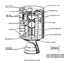
Block II service module interior components
Structure [edit]
The service module was an unpressurized cylindrical structure with a diameter of 12 feet 10 inches (iii.91 m) and fourteen anxiety 10 inches (4.52 m) long. The service propulsion engine nozzle and heat shield increased the total height to 24 feet vii inches (7.49 m). The interior was a unproblematic structure consisting of a central tunnel section 44 inches (i.1 k) in diameter, surrounded by six pie-shaped sectors. The sectors were topped by a forward bulkhead and fairing, separated by 6 radial beams, covered on the exterior past four honeycomb panels, and supported by an aft bulkhead and engine estrus shield. The sectors were not all equal lx° angles, but varied according to required size.
- Sector one (50°) was originally unused, so information technology was filled with ballast to maintain the SM's center-of gravity.
- On the last three lunar landing (I-J class) missions, it carried the scientific instrument module (SIM) with a powerful Itek 24 inches (610 mm) focal length camera originally adult for the Lockheed U-2 and SR-71 reconnaissance aircraft. The photographic camera photographed the Moon; had the S-IVB failed to fire causing the CSM to not leave globe orbit, astronauts would have used information technology to photograph the Earth.[15] [xvi] SIM also had other sensors and a subsatellite.
- Sector 2 (70°) contained the service propulsion arrangement (SPS) oxidizer sump tank, and then called because it straight fed the engine and was kept continuously filled past a separate storage tank, until the latter was empty. The sump tank was a cylinder with hemispherical ends, 153.8 inches (3.91 m) high, 51 inches (i.3 m) in diameter, and contained 13,923 pounds (6,315 kg) of oxidizer. Its total volume was 161.48 cu ft (4.573 g3)
- Sector 3 (60°) contained the SPS oxidizer storage tank, which was the same shape as the sump tank but slightly smaller at 154.47 inches (three.924 m) high and 44 inches (i.1 m) in diameter, and held xi,284 pounds (5,118 kg) of oxidizer. Its full volume was 128.52 cu ft (3.639 m3)
- Sector 4 (50°) contained the electrical power system (EPS) fuel cells with their hydrogen and oxygen reactants.
- Sector five (70°) contained the SPS fuel sump tank. This was the same size every bit the oxidizer sump tank and held eight,708 pounds (3,950 kg) of fuel.
- Sector 6 (60°) independent the SPS fuel storage tank, also the same size equally the oxidizer storage tank. It held 7,058 pounds (iii,201 kg) of fuel.
The forward fairing measured 1 human foot 11 inches (58 cm) long and housed the reaction control system (RCS) computer, power distribution block, ECS controller, separation controller, and components for the high-proceeds antenna, and included eight EPS radiators and the umbilical connection arm containing the main electrical and plumbing connections to the CM. The fairing externally contained a retractable frontwards-facing spotlight; an EVA floodlight to aid the command module airplane pilot in SIM moving-picture show retrieval; and a flashing rendezvous beacon visible from 54 nautical miles (100 km) away as a navigation help for rendezvous with the LM.
The SM was connected to the CM using iii tension ties and six compression pads. The tension ties were stainless steel straps bolted to the CM's aft heat shield. It remained attached to the command module throughout most of the mission, until existence jettisoned just prior to re-entry into the Earth's atmosphere. At jettison, the CM umbilical connections were cut using a pyrotechnic-activated guillotine associates. Following jettison, the SM aft translation thrusters automatically fired continuously to distance it from the CM, until either the RCS fuel or the fuel cell power was depleted. The roll thrusters were besides fired for five seconds to make sure information technology followed a dissimilar trajectory from the CM and faster break-up on re-entry.
Service propulsion system [edit]

Apollo Service Module Propulsion System
The service propulsion system (SPS) engine was originally designed to lift the CSM off the surface of the Moon in the direct rise mission mode,[17] The engine selected was the AJ10-137,[18] which used Aerozine l equally fuel and nitrogen tetroxide (Northward2O4) every bit oxidizer to produce 20,500 lbf (91 kN) of thrust. A contract was signed in April 1962 for the Aerojet-General visitor to beginning developing the engine, resulting in a thrust level twice what was needed to achieve the lunar orbit rendezvous (LOR) mission mode officially chosen in July of that yr.[19] The engine was really used for mid-course corrections between the Earth and Moon, and to place the spacecraft into and out of lunar orbit. It also served as a retrorocket to perform the deorbit burn for World orbital flights.
The propellants were pressure-fed to the engine past 39.2 cubic feet (ane.11 m3) of gaseous helium at three,600 pounds per foursquare inch (25 MPa), carried in two twoscore-inch (one.0 m) diameter spherical tanks.[xx]
The frazzle nozzle measured 152.82 inches (iii.882 m) long and 98.48 inches (two.501 m) broad at the base. It was mounted on ii gimbals to keep the thrust vector aligned with the spacecraft's heart of mass during SPS firings. The combustion chamber and pressurant tanks were housed in the primal tunnel.
Reaction control system [edit]

RCS quad containing four R-4D thrusters, as used on the Apollo Service Module
Four clusters of four reaction control system (RCS) thrusters were installed around the upper department of the SM every 90°. The sixteen-thruster arrangement provided rotation and translation control in all three spacecraft axes. Each R-4D thruster generated 100 pounds-force (440 Due north) of thrust, and used monomethylhydrazine (MMH) as fuel and nitrogen tetroxide (NTO) as oxidizer. Each quad assembly measured viii by 3 feet (2.44 by 0.91 m) and had its own fuel tanks, oxidizer tanks, helium pressurant tank, and associated valves and regulators.
Each cluster of thrusters had its own independent chief fuel (MMH) tank containing 69.1 pounds (31.three kg), secondary fuel tank containing 45.2 pounds (20.five kg), primary oxidizer tank containing 137.0 pounds (62.i kg), and secondary oxidizer tank containing 89.ii pounds (40.5 kg). The fuel and oxidizer tanks were pressurised by a single liquid helium tank containing 1.35 pounds (0.61 kg).[21] Back flow was prevented by a series of check valves, and dorsum flow and ullage requirements were resolved past containing the fuel and oxidizer in Teflon bladders which separated the propellants from the helium pressurant.[21]
All of the elements were duplicated, resulting in four completely independent RCS clusters. Only two adjacent operation units were needed to let complete mental attitude control.[21]
The lunar module used a similar four-quad arrangement of the identical thruster engines for its RCS.
Electrical power system [edit]

Three of these fuel cells supplied electric power to the spacecraft on lunar flights.
Electrical power was produced by 3 fuel cells, each measuring 44 inches (1.ane m) tall by 22 inches (0.56 m) in diameter and weighing 245 pounds (111 kg). These combined hydrogen and oxygen to generate electrical power, and produced potable water as a byproduct. The cells were fed by two hemispherical-cylindrical 31.75-inch (0.806 m) diameter tanks, each holding 29 pounds (13 kg) of liquid hydrogen, and 2 spherical 26-inch (0.66 m) diameter tanks, each holding 326 pounds (148 kg) of liquid oxygen (which too supplied the environmental command system).
On the flight of Apollo 13, the EPS was disabled by an explosive rupture of one oxygen tank, which punctured the second tank and led to the loss of all oxygen. Afterwards the accident, a third oxygen tank was added to obviate performance below 50% tank chapters. That allowed the elimination of the tank's internal stirring-fan equipment, which had contributed to the failure.
As well starting with Apollo 14, a 400 Ah auxiliary battery was added to the SM for emergency use. Apollo 13 had drawn heavily on its entry batteries in the get-go hours subsequently the explosion, and while this new battery could not power the CM for more than v–10 hours information technology would buy time in the event of a temporary loss of all iii fuel cells. Such an event had occurred when Apollo 12 was struck twice by lightning during launch.
Ecology control system [edit]
Cabin atmosphere was maintained at 5 pounds per square inch (34 kPa) of pure oxygen from the aforementioned liquid oxygen tanks that fed the electrical power system's fuel cells. Potable water supplied by the fuel cells was stored for drinking and food preparation. A thermal control organisation using a mixture of h2o and ethylene glycol as coolant dumped waste heat from the CM motel and electronics to outer space via two 30-square-foot (2.viii mii) radiators located on the lower section of the exterior walls, one covering sectors 2 and three and the other covering sectors v and 6.[22]
Communications system [edit]

VHF scimitar antennas mounted on the Service Module.
Brusk-range communications betwixt the CSM and LM employed two VHF scimitar antennas mounted on the SM just above the ECS radiators. These antennas were originally located on the Cake I control module and performed a double office every bit aerodynamic strakes to stabilize the capsule afterwards a launch abort. The antennas were moved to the Block Ii service module when this role was found unnecessary.
A steerable unified S-band loftier-gain antenna for long-range communications with Earth was mounted on the aft bulkhead. This was an array of four 31-inch (0.79 thousand) diameter reflectors surrounding a single 11-inch (0.28 m) square reflector. During launch it was folded down parallel to the main engine to fit inside the Spacecraft-to-LM Adapter (SLA). After CSM separation from the SLA, it deployed at a right angle to the SM.
Iv omnidirectional South-band antennas on the CM were used when the attitude of the CSM kept the high-gain antenna from being pointed at Globe. These antennas were too used between SM jettison and landing.[23]
Specifications [edit]
- Length: 24.8 ft (vii.6 m)
- Diameter: 12.8 ft (three.nine m)
- Mass: 54,060 lb (24,520 kg)
- Structure mass: 4,200 lb (1,900 kg)
- Electrical equipment mass: 2,600 lb (1,200 kg)
- Service Propulsion (SPS) engine mass: 6,600 lb (3,000 kg)
- SPS engine propellants: 40,590 lb (18,410 kg)
- RCS thrust: 2 or 4 × 100 lbf (440 Northward)
- RCS propellants: MMH/N
2 O
iv - SPS engine thrust: 20,500 lbf (91,000 Due north)
- SPS engine propellants: (UDMH/N
2 H
4 )/N
ii O
4 - SPS I sp: 314 s (3,100 Northward·s/kg)
- Spacecraft delta-v: 9,200 ft/s (2,800 m/due south)
- Electrical system: iii 1.four kW 30 V DC fuel cells
Modifications for Saturn IB missions [edit]
Apollo CSM in white for a Skylab mission, docked to the Skylab space station
The payload adequacy of the Saturn IB launch vehicle used to launch the Depression Earth Orbit missions (Apollo 1 (planned), Apollo 7, Skylab 2, Skylab three, Skylab four, and Apollo-Soyuz) could non handle the 66,900-pound (30,300 kg) mass of the fully fueled CSM. This was not a problem, because the spacecraft delta-5 requirement of these missions was much smaller than that of the lunar mission; therefore they could be launched with less than half of the total SPS propellant load, by filling only the SPS sump tanks and leaving the storage tanks empty. The CSMs launched in orbit on Saturn IB ranged from 32,558 pounds (fourteen,768 kg) (Apollo-Soyuz), to 46,000 pounds (21,000 kg) (Skylab 4).
The omnidirectional antennas sufficed for footing communications during the Earth orbital missions, so the high-gain S-band antenna on the SM was omitted from Apollo 1, Apollo 7, and the three Skylab flights. Information technology was restored for the Apollo-Soyuz mission to communicate through the ATS-6 satellite in geostationary orbit, an experimental precursor to the electric current TDRSS system.
On the Skylab and Apollo-Soyuz missions, some additional dry weight was saved by removing the otherwise empty fuel and oxidizer storage tanks (leaving the partially filled sump tanks), along with one of the two helium pressurant tanks.[24] This permitted the improver of some extra RCS propellant to let for use as a backup for the deorbit burn in case of possible SPS failure.[25]
Since the spacecraft for the Skylab missions would non be occupied for most of the mission, in that location was lower demand on the power system, so one of the 3 fuel cells was deleted from these SMs. The control module was as well partially painted white, to provide passive thermal control for the extended time it would remain in orbit.
The control module could be modified to carry extra astronauts as passengers by adding jump seat couches in the aft equipment bay. CM-119 was fitted with two leap seats as a Skylab Rescue vehicle, which was never used.[26]
Major differences betwixt Cake I and Cake Two [edit]
Command module [edit]

Cake I control module outside
- The Block 2 used a one-piece, quick-release, outward opening hatch instead of the 2-piece plug hatch used on Cake I, in which the inner piece had to be unbolted and placed inside the cabin in order to enter or exit the spacecraft (a flaw that doomed the Apollo 1 crew). The Block 2 hatch could be opened chop-chop in case of an emergency. (Both hatch versions were covered with an extra, removable section of the Boost Protective Embrace which surrounded the CM to protect it in example of a launch abort.)
- The Block I forrard access tunnel was smaller than Block Two, and intended only for emergency coiffure egress later splashdown in case of bug with the main hatch. It was covered by the nose of the forrad heat shield during flying. Block II contained a shorter frontward oestrus shield with a flat removable hatch, below a docking band and probe mechanism which captured and held the LM.
- The aluminized PET moving picture layer, which gave the Cake 2 estrus shield a shiny mirrored appearance, was absent on Block I, exposing the light gray epoxy resin material, which on some flights was painted white.
- The Cake I VHF scimitar antennas were located in ii semicircular strakes originally thought necessary to help stabilize the CM during reentry. However, the uncrewed reentry tests proved these to be unnecessary for stability, and likewise aerodynamically ineffective at high fake lunar reentry speeds. Therefore, the strakes were removed from Cake II and the antennas were moved to the service module.
- The Cake I CM/SM umbilical connector was smaller than on Block Ii, located near the crew hatch instead of virtually 180 degrees away from it. The separation point was between the modules, instead of the larger hinged arm mounted on the service module, separating at the CM sidewall on Cake Two.
- The two negative pitch RCS engines located in the forward compartment were arranged vertically on Block I, and horizontally on Block II.
Service module [edit]

Block I service module interior components
- On the Apollo half-dozen uncrewed Block I flight, the SM was painted white to match the command module'south appearance. On Apollo 1, Apollo 4, and all the Block 2 spacecraft, the SM walls were left unpainted except for the EPS and ECS radiators, which were white.
- The EPS and ECS radiators were redesigned for Block II. Block I had three larger EPS radiators located on Sectors i and 4. The ECS radiators were located on the aft section of Sectors two and 5.
- The Block I fuel cells were located at the aft bulkhead in Sector four, and their hydrogen and oxygen tanks were located in Sector 1.
- Block I had slightly longer SPS fuel and oxidizer tanks which carried more propellant than Block 2.
- The Block Ii aft rut shield was a rectangular shape with slightly rounded corners at the propellant tank sectors. The Block I shield was the same basic shape, but bulged out slightly near the ends more similar an hourglass or effigy viii, to cover more of the tanks.
CSMs produced [edit]
| Serial number | Proper noun | Use | Launch date | Electric current location | Image |
|---|---|---|---|---|---|
| Block I [27] [28] [29] | |||||
| CSM-001 | systems compatibility test vehicle | scrapped [thirty] | |||
| CSM-002 | A-004 flying | January 20, 1966 | Command module on display at Cradle of Aviation, Long Island, New York[31] |  | |
| CSM-004 | static and thermal structural footing tests | scrapped [29] | |||
| CSM-006 | used for demonstrating tumbling debris removal system | Command module scrapped;[32] service module (redesignated as SM-010)[28] on display at U.S. Space & Rocket Centre, Huntsville, Alabama[33] | |||
| CSM-007 | various tests including audio-visual vibration and driblet tests, and water egress grooming. CM was refitted with Cake II improvements.[34] Underwent testing for Skylab at the McKinley Climatic Laboratory, Eglin AFB, Florida, 1971–1973. | Command module on brandish at Museum of Flight, Seattle, Washington[35] |  | ||
| CSM-008 | consummate systems spacecraft used in thermal vacuum tests | scrapped [xxx] | |||
| CSM-009 | Equally-201 flying and driblet tests | February 26, 1966 | Control module on display at Strategic Air and Infinite Museum, adjacent to Offutt Air Force Base of operations in Ashland, Nebraska[36] |  | |
| CSM-010 | Thermal test (command module redesignated every bit CM-004A / BP-27 for dynamic tests);[37] service module never completed [28] | Command module on brandish at U.Southward. Space & Rocket Center, Huntsville, Alabama [30] |  | ||
| CSM-011 | Equally-202 flight | August 25, 1966 | Control module on display on the USS Hornet museum at the onetime Naval Air Station Alameda, Alameda, California[38] |  | |
| CSM-012 | Apollo 1; the command module was severely damaged in the Apollo one burn down | Command module in storage at the Langley Research Center, Hampton, Virginia;[39] 3-office door hatch on display at Kennedy Space Center;[40] service module scrapped [thirty] |  | ||
| CSM-014 | Command module disassembled as part of Apollo i investigation. Service module (SM-014) used on Apollo 6 mission. Control module (CM-014) subsequently modified and used for ground testing (every bit CM-014A).[28] | Scrapped May 1977.[27] | |||
| CSM-017 | CM-017 flew on Apollo 4 with SM-020 after SM-017 was destroyed in a propellant tank explosion during ground testing.[28] [41] | November 9, 1967 | Command module on brandish at Stennis Space Centre, Bay St. Louis, Mississippi[42] |  | |
| CSM-020 | CM-020 flew on Apollo half dozen with SM-014.[28] | April iv, 1968 | Control module on brandish at Fernbank Scientific discipline Heart, Atlanta |  | |
| Block II[43] [44] | |||||
| CSM-098 | 2TV-ane (Block Ii Thermal Vacuum no.1) [45] | used in thermal vacuum tests | CSM on display at University of Science Museum, Moscow, Russian federation as part of the Apollo Soyuz Test Projection display.[29] | ||
| CM-099 | 2S-1 [45] | Skylab flying crew interface grooming;[45] bear on tests [28] | scrapped[45] | ||
| CSM-100 | 2S-2 [45] | static structural testing [28] | Command module "transferred to Smithsonian as an artifact", service module on display at New Mexico Museum of Space History[45] | ||
| CSM-101 | Apollo 7 | Oct 11, 1968 | Command module was on display at National Museum of Scientific discipline and Technology, Ottawa, Ontario, Canada from 1974 until 2004, now at the Frontiers of Flying Museum, Dallas, Texas after thirty years of being on loan.[46] |  | |
| CSM-102 | Launch Complex 34 checkout vehicle | Command module scrapped;[47] service module is at JSC on top of the Little Joe 2 in Rocket Park with Banality Plate 22 command module.[48] |  | ||
| CSM-103 | Apollo 8 | December 21, 1968 | Command module on display at the Museum of Scientific discipline and Industry in Chicago[44] |  | |
| CSM-104 | Gumdrop | Apollo 9 | March 3, 1969 | Command module on display at San Diego Air and Space Museum[44] |  |
| CSM-105 | acoustic tests | On display at National Air and Space Museum, Washington, D.C. equally role of the Apollo Soyuz Exam Project display.[49] (Photo) | | ||
| CSM-106 | Charlie Brown | Apollo 10 | May 18, 1969 | Control module on display at Science Museum, London[44] |  |
| CSM-107 | Columbia | Apollo 11 | July 16, 1969 | Command module on display at National Air and Space Museum, Washington, D.C.[44] |  |
| CSM-108 | Yankee Clipper | Apollo 12 | November fourteen, 1969 | Command module on display at Virginia Air & Space Centre, Hampton, Virginia;[44] previously on display at the National Naval Aviation Museum at Naval Air Station Pensacola, Pensacola, Florida (exchanged for CSM-116) | 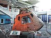 |
| CSM-109 | Odyssey | Apollo xiii | April 11, 1970 | Command module on display at Kansas Cosmosphere and Infinite Center[44] | 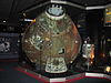 |
| CSM-110 | Kitty Hawk | Apollo 14 | January 31, 1971 | Command module on display at the Kennedy Infinite Center[44] | 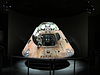 |
| CSM-111 | Apollo Soyuz Examination Project | July 15, 1975 | Command module currently on brandish at California Science Center in Los Angeles, California[50] [51] [52] (formerly displayed at the Kennedy Infinite Center Visitor Circuitous) |  | |
| CSM-112 | Endeavour | Apollo fifteen | July 26, 1971 | Control module on display at National Museum of the United States Air Strength, Wright-Patterson Air Force Base of operations, Dayton, Ohio[44] |  |
| CSM-113 | Casper | Apollo 16 | April 16, 1972 | Command module on display at U.S. Space & Rocket Center, Huntsville, Alabama[44] |  |
| CSM-114 | America | Apollo 17 | December 7, 1972 | Command module on display at Infinite Center Houston, Houston, Texas[44] |  |
| CSM-115 | Apollo 19[53] (canceled) | Never fully completed[54] | |||
| CSM-115a | Apollo 20[55] (canceled) | Never fully completed[54] – service module does not accept its SPS nozzle installed. On display as part of the Saturn Five display at Johnson Space Center, Houston, Texas; command module restored in 2005 prior to the dedication of the JSC Saturn Five Center[56] [a] | 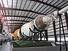 | ||
| CSM-116 | Skylab 2 | May 25, 1973 | Control module on display at National Museum of Naval Aviation, Naval Air Station Pensacola, Pensacola, Florida[58] | 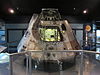 | |
| CSM-117 | Skylab 3 | July 28, 1973 | Command module on display at Great Lakes Science Center, current location of the NASA Glenn Inquiry Eye Visitor Middle, Cleveland, Ohio[59] |  | |
| CSM-118 | Skylab four | Nov 16, 1973 | Command module on display at Oklahoma History Heart[60] (formerly displayed at the National Air and Space Museum, Washington, D.C.)[61] |  | |
| CSM-119 | Skylab Rescue and ASTP fill-in | On display at the Kennedy Space Center[62] |  | ||

World map showing locations of Apollo command and service modules (along with other hardware).
Run across also [edit]
- Orbital module
- Reentry capsule
- Infinite capsule
- Space accommodate
- Infinite exploration
- U.S. Space Exploration History on U.S. Stamps
- Apollo Lunar Module
Footnotes [edit]
Notes
- ^ Some sources listed 2 separate vehicles, CSM-115 and CSM-115a;[57] restoration work of the control module in Johnson Space Center proved the command module is numbered CM-115a.[56]
Citations
- ^ "Aerojet AJ10-137 Archives".
- ^ Portree, David Southward. F. (September ii, 2013). "Project Olympus (1962)". Wired. ISSN 1059-1028. Retrieved February 25, 2020.
- ^ "ch1". history.nasa.gov . Retrieved February 25, 2020.
- ^ Courtney G Brooks; James M. Grimwood; Loyd S. Swenson (1979). "Contracting for the Control Module". Chariots for Apollo: A History of Manned Lunar Spacecraft. NASA. ISBN0-486-46756-2. Archived from the original on February ix, 2008. Retrieved January 29, 2008.
- ^ Courtney One thousand Brooks; James Grand. Grimwood; Loyd Due south. Swenson (1979). "Control Modules and Program Changes". Chariots for Apollo: A History of Manned Lunar Spacecraft. NASA. ISBN0-486-46756-ii. Archived from the original on February 9, 2008. Retrieved January 29, 2008.
- ^ Morse, Mary Louise; Trophy, Jean Kernahan (September 20, 2007). The Apollo Spacecraft: A Chronology. SP-4009II. Vol. II, Part 2(C): Developing Hardware Distinctions. NASA.
- ^ Orloff, Richard (1996). Apollo by the Numbers (PDF). National Aeronautics and Space Administration. p. 22.
- ^ "NASA New Start Inflation Indices". National Helmsmanship and Infinite Administration. Retrieved May 23, 2016.
- ^ "Apollo 11 Press Kit". No. 69–83K. NASA. July 6, 1969.
- ^ a b c d "CSM06 Command Module Overview pp. 39–52" (PDF). National Aeronautics and Space Administration. Retrieved Nov 1, 2016.
- ^ Hillje, Ernest R., "Entry Aerodynamics at Lunar Return Conditions Obtained from the Flying of Apollo four (As-501)," NASA TN D-5399, (1969).
- ^ Bloom, Kenneth (January 1, 1971). The Apollo docking system (Technical report). Northward American Rockwell Corporation. 19720005743.
- ^ "Apollo CM". Astronautix.com. Archived from the original on December 28, 2016. Retrieved June 7, 2020.
- ^ Orloff, Richard (2000). Apollo by the numbers : a statistical reference (PDF). Washington, D.C: National Helmsmanship and Space Administration. p. 277. ISBN0-16-050631-X. OCLC 44775012.
- ^ Twenty-four hour period, Dwayne (May 26, 2009). "Making lemons into lemonade". The Space Review . Retrieved July 10, 2020.
- ^ Day, Dwayne Allen (June 11, 2012). "Out of the blackness". The Infinite Review . Retrieved June 11, 2012.
- ^ Wilford, John (1969). We Attain the Moon: The New York Times Story of Man's Greatest Chance. New York: Bantam Paperbacks. p. 167. ISBN 0-373-06369-0.
- ^ "Apollo CSM". Encyclopedia Astronautica. Archived from the original on December 17, 2007.
- ^ "Apollo CSM SPS". Encyclopedia Astronautica. Archived from the original on February ane, 2010.
- ^ "Apollo Operations Handbook, SM2A-03-Block II-(one)" (PDF). NASA. Department 2.iv. Archived from the original on July 3, 2013.
- ^ a b c SM2A-03-Cake II-(one), Apollo Operations Handbook (PDF). National Helmsmanship and Space Administration. 1969. p. 8. Retrieved August xiii, 2017.
- ^ "Apollo Operations Handbook, SM2A-03-Cake Ii-(1)" (PDF). NASA. Department 2.7. Archived from the original on July 3, 2013.
- ^ "Nasa CSM/LM advice" (PDF) . Retrieved Dec xx, 2016.
- ^ "Reduced Apollo Block 2 service propulsion arrangement for Saturn IB Missions". Encyclopedia Astronautica. Archived from the original on February 1, 2010.
- ^ Gatland, Kenneth (1976). Manned Spacecraft, Second Revision. New York: Macmillan Publishing Co. p. 292. ISBN0-02-542820-9.
- ^ " Mission Requirements, Skylab Rescue Mission, SL-R" NASA, 24 Baronial 1973.
- ^ a b APOLLO/SKYLAB ASTP AND SHUTTLE --ORBITER MAJOR END ITEMS (PDF). NASA Johnson Space Eye. 1978. , p. iv
- ^ a b c d e f g h "CSM Contract" (PDF). NASA.
- ^ a b c "A Field Guide to American Spacecraft". Retrieved June 7, 2020.
- ^ a b c d Johnson Space Heart 1978, p. xiv.
- ^ "Rockwell Command Module 002 at the Cradle of Aviation Museum". Retrieved June 7, 2020.
- ^ Johnson Infinite Center 1978, p. 13.
- ^ Johnson Space Center 1978, pp. 13, 17.
- ^ These included the coiffure couches, quick escape hatch, and metallic oestrus shield blanket. See Apollo command module (prototype @ Wikimedia Commons).
- ^ Gerard, James H. (Nov 22, 2004). "CM-007". A Field Guide to American Spacecraft.
- ^ "Apollo Control Space Module (CSM 009)". Strategic Air Command & Aerospace Museum . Retrieved April 21, 2020.
- ^ Johnson Space Center 1978, p. 14, 17.
- ^ "Permanent Exhibits". USS Hornet museum. Retrieved October 22, 2016.
the Apollo Command Module – CM-011. Information technology was used for the uncrewed mission AS-202 on Baronial 26, 1966
- ^ Tennant, Diane (February 17, 2007). "Burned Apollo I capsule moved to new storage facility in Hampton". PilotOnline.com . Retrieved June 9, 2012.
- ^ "50 years later, NASA displays fatal Apollo capsule". The Horn News. January 25, 2017. Retrieved March 13, 2019.
- ^ Wade, Marking (Dec 10, 1999). "CSM Block I". Encyclopedia Astronautica.
- ^ "Apollo four sheathing from outset Saturn V launch lands at Infinity Science Center". Collectspace.com . Retrieved June 7, 2020.
- ^ "Apollo Command and Service Module Documentation". NASA.
- ^ a b c d e f g h i j k "Location of Apollo Command Modules". Smithsonian National Air and Infinite Museum. Retrieved Baronial 27, 2019.
- ^ a b c d eastward f Johnson Infinite Center 1978, p. 4.
- ^ "Apollo vii Command Module and Wally Schirra'due south Training Suit Leave Science and Tech Museum After 30 Years". Canada Science and Engineering science Museum. March 12, 2004. Archived from the original on August 17, 2010. Retrieved July xix, 2009.
- ^ Johnson Infinite Center 1978, p. five.
- ^ Gerard, James H. (July xi, 2007). "BP-22". A Field Guide to American Spacecraft.
- ^ Johnson Infinite Center 1978, pp. 4, 5.
- ^ Pearlman, Robert (February 23, 2018). "Historic Apollo-Soyuz Spacecraft Gets New Display at CA Science Middle". Space.com . Retrieved March 20, 2018.
- ^ "Apollo-Soyuz Command Module". californiasciencecenter.org . Retrieved March 20, 2018.
- ^ Pearlman, Robert. "Apollo-Soyuz spacecraft gets new display at CA Science Center". collectSPACE . Retrieved March 20, 2018.
- ^ United States. Congress. House. Committee on Science and Astronautics (1970). 1971 NASA Dominance: Hearings, Xc-first Congress, 2nd Session, on H.R. 15695 (superseded by H.R. 16516). U.Southward. Authorities Printing Office. p. 884.
- ^ a b United States. Congress. Firm. Committee on Science and Astronautics (1973). 1974 NASA Authorization: Hearings, 90-third Congress, First Session, on H.R. 4567 (superseded by H.R. 7528). U.S. Government Printing Office. p. 1272.
- ^ Shayler, David (2002). Apollo: The Lost and Forgotten Missions. Springer Science & Business Media. p. 271. ISBNane-85233-575-0.
- ^ a b Gerard, Jim. "A Field Guide to American Spacecraft". www.americanspacecraft.com . Retrieved January 22, 2018.
- ^ Johnson Space Center 1978, p. 6
- ^ "Item - National Naval Aviation Museum". National Naval Aviation Museum. September 5, 2015. Archived from the original on September 5, 2015. Retrieved June 8, 2020.
{{cite web}}: CS1 maint: unfit URL (link) - ^ Navratil, Liz (June 23, 2010). "Skylab space sheathing lands at Cleveland's Great Lakes Science Center". Cleveland.com . Retrieved April 15, 2019.
- ^ McDonnell, Brandy (November 17, 2020). "Oklahoma History Center celebrating 15th anniversary with gratuitous admission, new exhibit 'Launch to Landing: Oklahomans and Infinite'". The Oklahoman . Retrieved December 10, 2020.
- ^ "Skylab 4 capsule to land in new exhibit at Oklahoma History Centre". Collect Space. August 28, 2020. Retrieved Dec 10, 2020.
- ^ Johnson Infinite Middle 1978, p. vii.

Did Sps Services Take Over Casper Loans,
Source: https://en.wikipedia.org/wiki/Apollo_command_and_service_module
Posted by: mcallisterhessium.blogspot.com
0 Response to "Did Sps Services Take Over Casper Loans"
Post a Comment